The Big Muff π Page
The Definitive Big Muff Resource and History
VISIT MY SWORDS, KNIVES and FANTASY ART WEBSITE www.kitrae.net
©Kit Rae. Last update June 2014
PART 1 • PART 2 • PART 3 • PART 4
WHY ARE THE TRANSISTORS LABELED IN THE REVERSE ORDER? - Note that Q1-Q4 and D1-D4 are labeled in reverse order from input to output on these schematics than they are on a typical schematic. This is due to the fact that they are printed in this order on the actial V1, V2, and V3 Big Muff PCB's. To keep it from being confusing for those reading their PCB's, since this is primarily a reference for vintage Big Muff owners, and to keep the EH tradition, we have used this order on all Big Muff schematics, including post 1980's Big Muffs. I have also tried to keep the part numbers consistent from schematic to schematic.
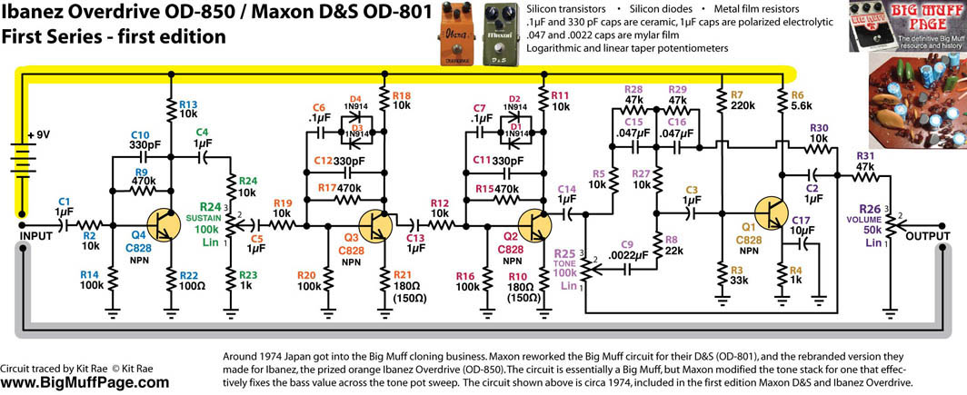
MAXON D&S / IBANEZ OVERDRIVE First Series - Around 1974 the japanese Big Muff cloning business increased heavily. Maxon cloned the Big Muff for their D&S (OD801), and the rebranded version they made for Ibanez, the famous Ibanez Overdrive (OD850). Maxon opted to alter the tone stack for this clone, fixing the bass value across the tone pot sweep, although listening to my OD-850, I think the traditional BMP tone stack would have worked fine. The whole high pass and low pass tone section is incorporated into the recovery stage. What this did was to make the bass and treble sides have a more useful range of sounds. The treble side retains some bass across the sweep, so it is not as ear piercing and trebly as a standard BMP when dialed completely to the treble side, nor do the highs seem to be completely removed when dialed fully to the bass side. It kind of makes finding the 'sweet spot' a bit different sounding than the traditional BMP tone stack, but that is what makes this version unique. The Maxon D&S reissued in 2009 is not exactly the same as this schematic. The Maxon D&S II is a completely different circuit, with no relation to a Big Muff.
Note the low 330pF filter caps at C10, C11, and C12, a value not found in original Big Muffs.
I have written more about Maxon and the Maxon/Ibanez Big Muff clones here.
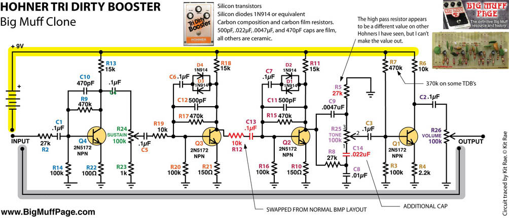
HOHNER TRI DIRTY BOOSTER - Another very good clone of the BMP. This one appeared on the market around 1974 or '75 from Hohner. Component values are similar to a few V1 schematics, but it does not follow any of them exactly. An extra .022µF cap was added in the tone section between lug 1 of the tone pot and R8, presumably to widen the tone pot sweep, although I hear little difference when it is removed.
I have written more about Hohner and the Tri Dirty Booster here.
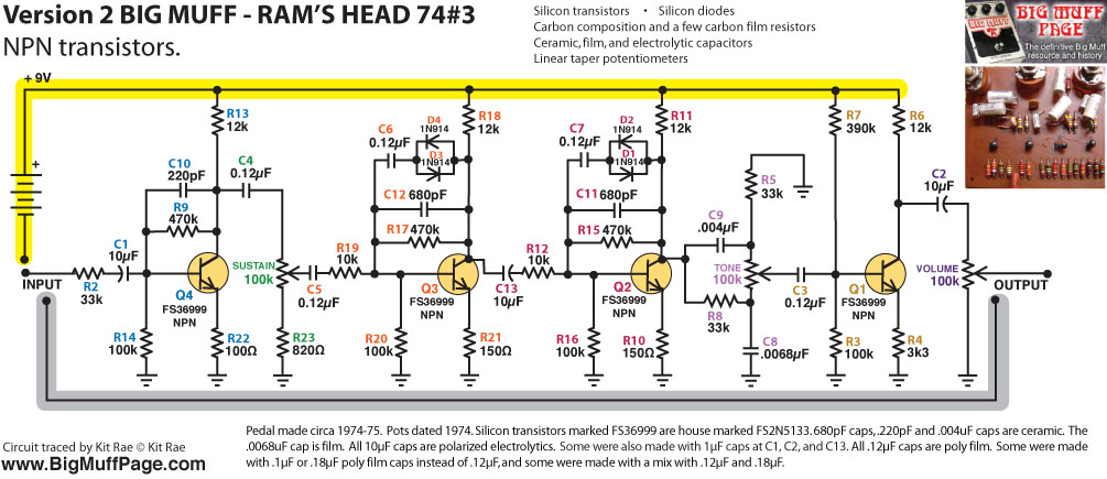
V2 "WHITE CAN" RAMS HEAD BIG MUFF PI - I believe this was the sixth in the sequence of circuit variants for the V2. It is also the second most common version of the V2 circuit made by Electro-Harmonix, after the '73 violet. Around 1974 EHX started using these large, barrel shaped, white axial poly film caps, which is the easiest way to identify this version. The 220pF filter cap in the first stage at C10 was unique to this version, as was the small .0068µF filter cap in the tone section. Those were nearly always .01µF. The input cap at C1 increased to 10µF and remained this value on many later V2 variants, allowing more bass into the circuit. For this version, C13 and the C2 output cap were also changed to 10µF for more bass going out of the circuit. The filter caps at C12 and C11 are 680pF, a value only found on this version, and the largest value EHX ever used. The 220pF cap in the first stage was used to sort of balance out the 680pF caps in the clipping stages, in an effort to keep the sound from being too different from the previous versions. The same circuit was also used in the Guild Foxey Lady version.
Many of these were also made with 1µF polarized electros at C1, C2, and C13, rather than 10µF. Another variant exists with the more common 470pF caps at C10, C11, and C12, but few were made. Polarized electros at C1, C2, and C13 also varied from 1µF to 10µF in that variant.
Note that most of the original Silicon diodes from this period are unknown, simply marked with a black band, but some are 1N125. 1N914 (shown on the schematic) and 1N4148 are some modern equivalents that work, but they may not be identical to the original diodes. The differences are minor, but diode types do affect the sound frequencies that are clipped.
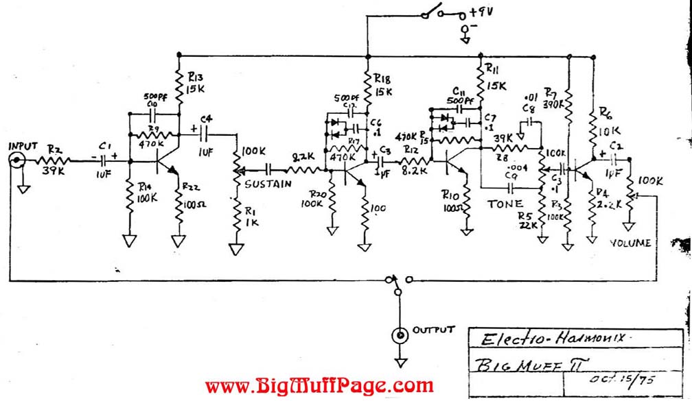
V2 RAMS HEAD BIG MUFF PI - This is an original EHX schematic dated October 15, 1975. At first glance this appears to be a 1973 violet era schemo, but closer inspection reveals the base and emitter resistors are all 100Ω, rather than 150Ω like the violet era. Both high and low pass tone resistors are mis-matched as they were on most V2's circa 1975-76, rather than matched in the '73 violets, and all previous Big Muffs. The filter caps are shown as 500pF like some early 1970's Big Muffs, but what EHX was actually using was 470 or 560pF. I have also never seen a 2.2k resistor at R7 in a V2 from this period. 2.7k was the smallest value used in the V2, and around 1974 3.3k became the standard for the output stage bias, so this 2.2k value is an oddity, or that exact value may simply have not been available. Otherwise, the values are more or less a mix of 1970s values. This schematic also shows the intended + direction for the polarized electros, always pointing to the nearest transistor. This was not always followed in production, but it seems to make little difference in a 9v battery powered circuit pointing either way.
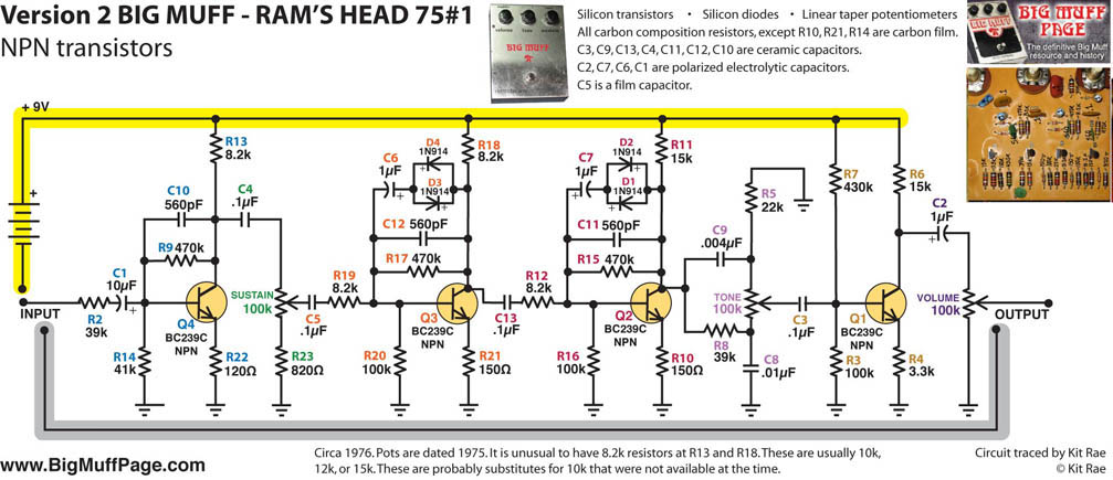
V2 RAMS HEAD BIG MUFF PI - This was probably the 14th in the sequence of circuit variants for the V2, circa 1976. Other than the 8.2k input resistors, which were usually 10 or 12k, and the small collector resistors at R13 and R11, this was similar to the other common 1976-76 V2 circuits. The 8.2k collectors resistors almost seem to be a mistake, but this was an actual production schematic. The reason may have been due to a surplus of 8.2k resistors or a shortage of 10k or 15k. One important change was making the tone stack resistors have mismatched values, where they had always been identical before. This opened the door for some slightly different voicings in the mid range scoop and the frequency levels in the high pass and low pass sides of the tone stack. The large 10µF input cap at C1 from the previous version remained.
Note that the original Silicon diodes are only marked with the black band. The actual diode types used are unknown. 1N914 (shown on the schematic) and 1N4148 are some modern equivalents that work, but they may not be identical to the original diodes. The differences are minor, but diode types do affect the sound frequencies that are clipped.
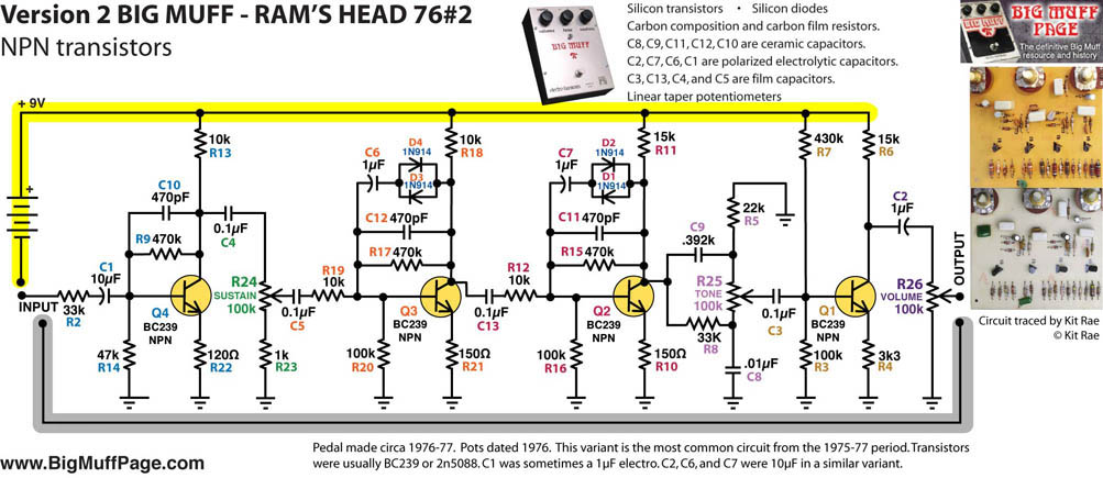
V2 "BOX CAP" RAMS HEAD BIG MUFF PI - This is the most common V2 from the 1975-77 period, probably the 15th variant. This "Box Cap" Ram's Head version is easily identified by the large white box caps used. Quanitites made seem to be almost as many as the "White Can" Ram's Head version shown above (74#3). Identical to 76#1 below, but with 33k input resistor and low pass tone resistors at R2 and R8, instead of 39k, and 470pF filter caps instead of 560pF at C10, 11 and 12. The C1 input cap was almost always a 10µF polarized electro. Some production of this version changed between 1µF and 10µF at C2, C6, and C7, and a few used 10µF for all C1, C2, C6, and C7 caps.
Thanks to aionfx.com, we now know that this was the variant Pete Cornish traced to make his P-1, a clone he originally made for David Gilmour. Depending on which origin story is correct, the P-1 was either an exact clone of David Gilmour's favorite Ram's Head Big Muff, or it was a clone of one of seven Big Muff's Gilmour sent to Pete for him to pick the best one and make a clone for David's pedalboard.
Note that some of the original Silicon diodes from this period are 1N925, 1N802 (gray/black/red bands) but others are unknown, simply marked with a black band. 1N914 (shown on the schematic) and 1N4148 are some modern equivalents that work, but they may not be identical to the original diodes. The differences are minor, but diode types do affect the sound frequencies that are clipped.
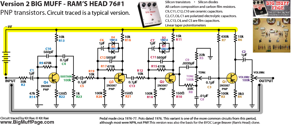
V2 RAMS HEAD BIG MUFF PI - Another typical V2 circuit from around 1976, probably the 16th variant. Very similar to the 75#1 schematic above, but this was a PNP version with 2N5087 transistors. Numerous clones were based on this version, including the BYOC Large Beaver. The C1 input cap was almost always sometimes a 10µF polarized electro on this variant.
Note that some of the original Silicon diodes from this period are 1N925, 1N802 (gray/black/red bands) but others are unknown, simply marked with a black band. 1N914 (shown on the schematic) and 1N4148 are some modern equivalents that work, but they may not be identical to the original diodes. The differences are minor, but diode types do affect the sound frequencies that are clipped.
VERSION 3 BIG MUFF PI - Approximately 10 circuit variants exist, each made in extended manufacturing runs.
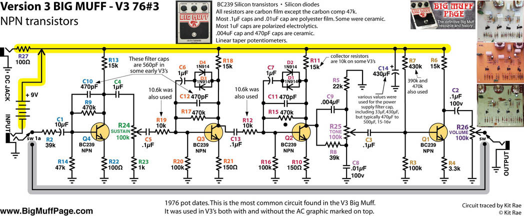
V3 BIG MUFF PI - The "V3" used the same PCB and enclosure as the V2, but graphics were changed, and for the first time a 9V AC adaptor jack was added, with a polarized cap (C14) and resistor (R27) for power filtering. Out of the 9 or 10 variants of the V3 circuit, this is the most common one made. Notations of the changes in the other V3 circuit variants are listed below. Frank Zappa had one of these in his 1988 custom effects rack, with huge 47k limiting resistors, which I have never seen in any other stock Big Muff.
Since some wall warts (AC to DC power adaptors) do not regulate and filter properly it was necessary for E-H to add some filtering to the circuit. Wall warts convert AC to DC using a bridge rectifier, but some of that rippling alternating current can still leak through the power supply rail into the direct current, creating 60 cycle hum noise in the audio signal. The 100Ω resistor at R27 is there to reduce that noisy AC. AC current sees a capacitor as a short circuit, so the big electrolytic cap on the +9v power supply at C14 was added to smoothly filter more of the AC ripple by draining the ripple peaks to ground, leaving (mostly) straight DC going through the circuit.
Note some of the original Silicon diodes were 1N4148 or 1N914, but others from this period are simply marked with a black band, so diode type is unknown. It is presumed these are similar in value to the known diode types, but they may not be identical to the original diodes. The differences are minor, but diode types do affect the sound frequencies that are clipped.
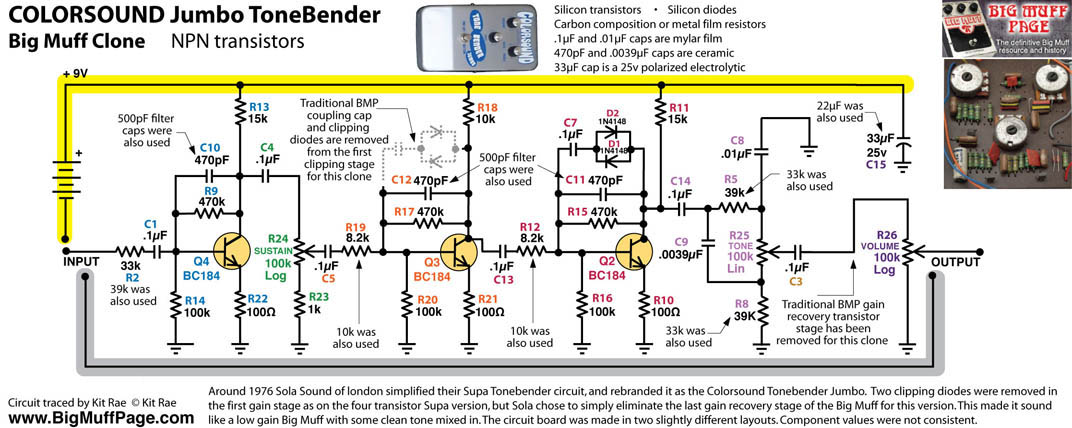
COLORSOUND JUMBO TONEBENDER Modified V3 Big Muff - Around 1976 Sola Sound of London modified their Big Muff clone, the Supa Tonebender, changing some component values, and entirely removing the gain recovery stage. The values in the Jumbo Tonebender were basically from a V3 era Big Muff. The purpose of the last stage in the original design was to recover some of the audio gain lost (approximately 8db) in the tone section, so removing it made for a very weak, low gain Muff. It almost sounds like some of the clean signal is mixed in with the distortion. This made for a muff that was rather lifeless for electric guitar leads and chords, but worked very well for bass guitar.
I have written more about Colorsound and the Jumbo Tonebender here.
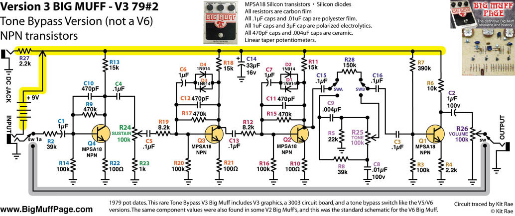
V3 BIG MUFF PI with TONE BYPASS - The very first circuit mod by EHX. A rare variant of the V3 circuit with tone bypass switching (C15, R28, switch) and power filtering (R27, C14), made simultaneously with the V4 and V5 op-amp versions. Many people think the tone bypass was added with the V5 Big Muff, but it actually first appeared in this V3 variant, circa 1979. It was simple switch in between C14 and C3 that completely bypassed the Big Muff tone control, making the tone pot inactive, flattening the EQ, and giving a slight volume boost. This variant used MPSA18 transistors, very rarely used in a BMP.
The exact circuit also appeared around 1976 in the V2 Big Muff enclosure, without the power filtering, tone bypass switching, and with different transistors. It was used in guitarist J Mascis' (Dinosaur jr) favorite Ram's Head Big Muff. The exact V3 tone bypass schematic later became the standard BMP circuit in the V6 Big Muff Pi, so the Mascis Muff is essentailly a V6. That may be why J likes that particular V2 so much. None of his other V1 and V2 BMP's have this circuit.
Note some of the original Silicon diodes were 1N4148 or 1N914, but others from this period are simply marked with a black band, so diode type is unknown. It is presumed these are similar in value to the known diode types, but they may not be identical to the original diodes. The differences are minor, but diode types do affect the sound frequencies that are clipped.
VERSION 6 BIG MUFF PI - Only one version of the circuit exists
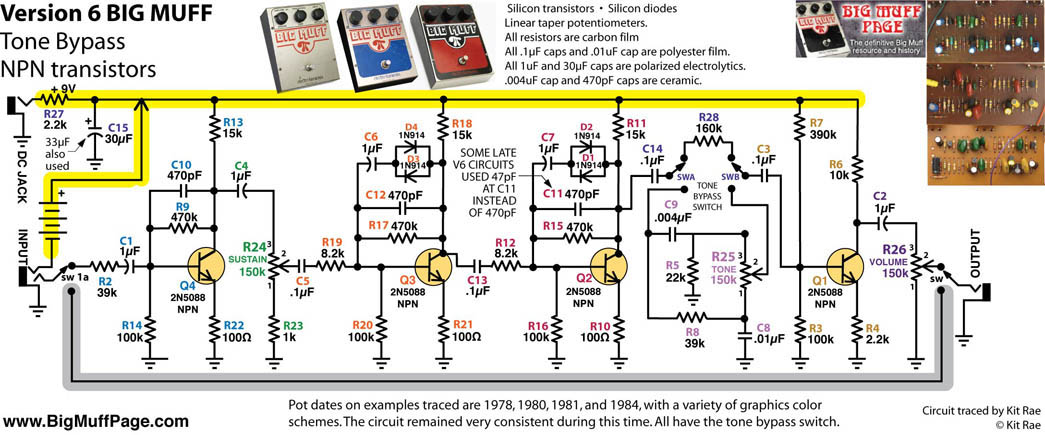
V6 BIG MUFF PI with TONE BYPASS - The common "V6" Big Muff circuit, circa 1979. The V3 tone bypass version had become standardized by this time so EHX reworked the old 3003 pcb layout into a smaller size, including the tone bypass (C14, R28, switch) and power fitering components (R27, C15), all on one board. The same pcb was also used in the LIttle Big Muff. Although there was the occasional part substituted for one of a similar value, this was the standard schematic used until Electro-Harmonix closed its doors and shut down in 1984. Other than the transistors used and power filterig components, the component values are identical to the rare V3 tone bypass version shown above.
Note some of the original Silicon diodes were 1N4148 or 1N914, but others from this period are simply marked with a black band, so diode type is unknown. It is presumed these are similar in value to the known diode types, but they may not be identical to the original diodes. The differences are minor, but diode types do affect the sound frequencies that are clipped.
Kit’s Secret Guitar, Gear, and Music Page
Guitar stuff, gear stuff, soundclips, videos, Gilmour/Pink Floyd stuff, photos and other goodies.
Copyright Kit Rae.
VISIT MY SWORDS, KNIVES and FANTASY ART WEBSITE www.kitrae.net


This page is not authorized, affiliated, or associated with Electro Harmonix in any way.
Website and contents ©2007 and ©2012 Kit Rae. All rights reserved. Linking to this website is allowed, but copying the text content is strictly prohibited without prior authorization. No part of this work may be reproduced, stored in a retrieval system, or transmitted in any other form, or by any means, electronic, mechanical, photocopying, recording, computer networking, or otherwise without prior permission in writing from the copyright holder(s).